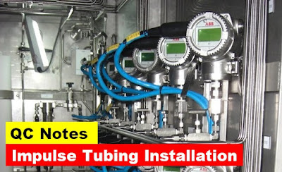
Aramco Standard Impulse Tubing Installation; Piping and Impulse tubing; Air distribution System;
This article is about Aramco Standard Impulse Tubing Installation, Tips for Installation, Piping and Impulse tubing, Air distribution System, Enclosures and focusing to the engineers, technicians and supervisors. You will find lot of documents related to this article. Just navigate our website www.QCSKILLS.com and find more articles.
Impulse Tubing
Installation:
Impulse lines for remote device should be as short as
possible, 3 feet for close-coupled transmitters and preferable not more than 20
feet (6 meters). For liquid measurement the lines should slope down at least 1
inch per foot from the orifice taps.
Tubing: Stainless steel tubing shall seamless, annealed,
minimum wall thick 1.24 mm as per ASTM A269 Gras IP – 316L.
Impulse Tubing Installation
Tips:
Slop of
Impulse tubing: Minimum of 1inch for every 1 meter towards tapping
point.
Bend: Minimum
bends length around 70 mm.
Test
Pressure of Impulse Line: 1.5 Times of the working pressure with 3 minute.
Instrument
Tubing size: ½ inch x 0.89 mm (wall thickness) = 0.035 Inches.
Piping and
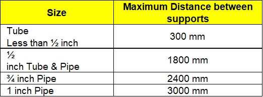
Impulse tubing shall be support as follows:
Piping and Impulse tubing
Air distribution System:
- All main and branch
headers shall be sloped {minimum 64 mm per 30 Meter (2.5 inches per 100 feet)}
and provided with low point drains.
- Supply takeoffs to
individual instruments (a line serving up to a maximum of four devices) shall
connect to the top of the branch header through a takeoff-line-size, full-bore
isolation valve.
- The minimum size of
supply takeoffs is ½ inch.
- Twenty percent (20%)
spare takeoff fittings and block valves shall be installed on the branch
header.
- Instrument air
piping shall not be pocketed. Instrument air piping shall not be installed
underground.
- The Piping route
shall avoid a harmful effect from a heat source (keep 150 mm minimum distance)
and not be under the process piping and equipment, which is
covered by the hot
or cold insulation materials.
Air Piping
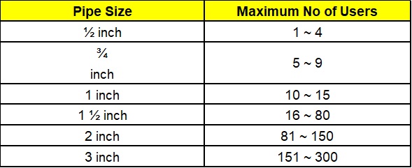
Maximum shall be No of Users as follows:
Enclosures:
Indoors and
Outdoors Plant Area:
Indoors: With in the
Perimeter of the Process Unit (NEMA 250 / NEMA ICS6)
Outdoor: Out side
the Perimeter of Process Area (IP54)
- Severe Corrosive
Environment (Industrial Area) NEMA Type 4X or IP66.
- Non Industrial Area
IP34.
- Name Plate Shall is
attached to the cabinets using stainless screws.
- Indoor Cabinets
shall be made of metal.
- The Cabinet shall be
a NEMA Type 1 as per NEMA 250 and NEMA ICS6.
- NEMA ICS6:
Enclosures for Industrial Controls and System.
- The Max Door Width
shall be 900 mm (36 Inch)
- The Marshalling
cabinets from the front surface to the surface of rear terminal block, shall
not be more than 46 cm (18 Inch).
- A minimum of prime,
undercoat & finishing coat of enamel or polish is required.
- Interior cabined
color shall be white or of light color such as light gray off.
- Name plate for
cabinets and panels letter height and spacing shall follow ISA RP 60.6
- Name Plate shall be
made from laminate Plastic, white – Black – White (Information engraved into
the black core) with white surface.


